工場フロアに冷却装置を追加するのは簡単そうに聞こえる。ユニットを購入し、どこかに設置し、配管と電源をつなぎ、スイッチを入れる。実際には、そんなに簡単なことはめったにない。チラーを設置する場所や、水をどのように機器に送るか、あるいは電気パネルに200アンペアのブレーカーをもう1つ置くスペースがあるかどうかなど、誰もよく考えていないうちにチラーが到着した施設をいくつか見てきた。このようなプロジェクトでは、土壇場で慌てることが多い。.
を統合する。 工業用チラーシステム は、設置そのものよりも準備に重点を置いている。スムーズに進むのは、最初のパイプを切断する前に、ユーティリティの接続からプロセス機器に至るまで、すべての経路を誰かが歩いたものだ。.
産業用チラーシステムのレイアウト計画
チラーの物理的な設置場所は、人々が思っている以上に重要だ。単に空いている一角を見つけるだけではないのだ。.
屋内配置と屋外配置
この決断が他のすべてを形作る。.
| プレースメント | 長所 | 短所 |
|---|---|---|
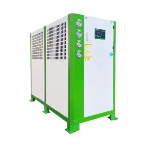
| 屋内 | 天候から保護され、監視が容易で、破壊行為のリスクが少ない。 | 換気が必要、床面積を取る、排熱の管理が必要 |
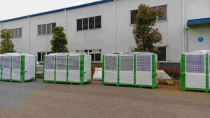
| アウトドア | 生産スペースを確保し、空冷ユニットの排熱を容易にする | 風雨にさらされるため、耐候性が必要。 |
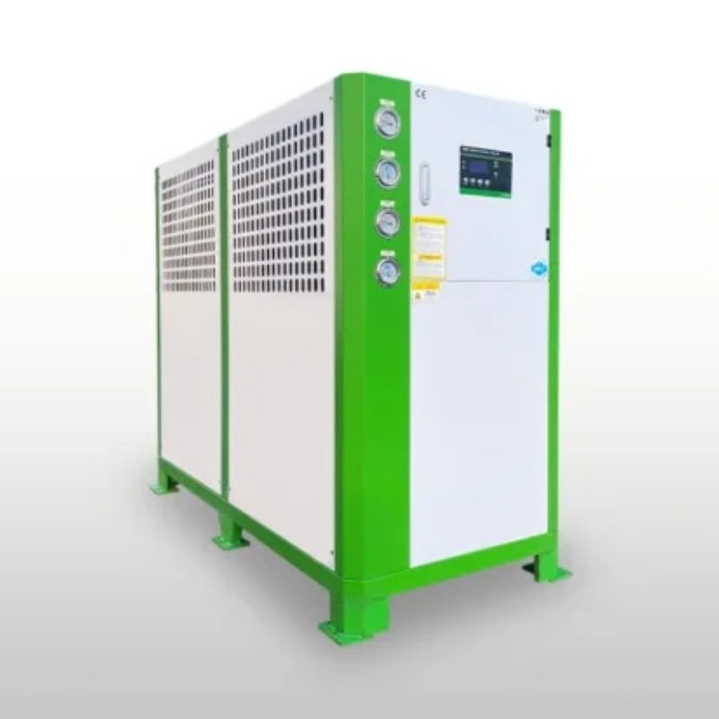
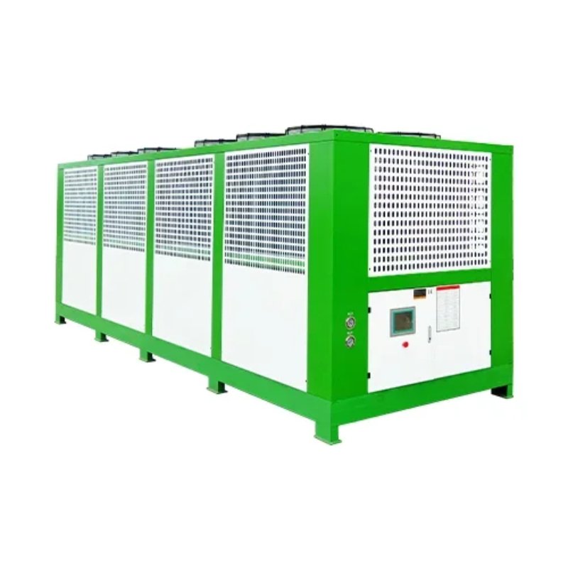
アン 空冷式チラー 屋外に設置する場合は、コンデンサーコイルの周囲に隙間が必要だ。空気の出入りができる十分なスペースと、コイルが汚れたときに高圧洗浄機で人が入れるスペースだ。屋内に設置する水冷式チラーには、冷却塔か冷却液クーラーが必要で、通常は屋上か屋外に設置する。.
プロセス機器への近接性
配管の引き回しはコスト増と圧力損失を生む。チラーが冷却対象機器から遠ければ遠いほど、ポンプは大型になる必要があり、途中で熱が奪われます。騒音やスペース、安全上の問題から、チラーをプロセスのすぐそばに設置できないこともあります。しかし、配管が1フィート増えるごとに、考える価値がある。.
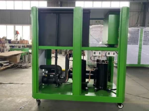
配管とポンプに関する考察
配管システムは、産業用チラーシステムと実際の機器をつなぐものです。また、多くの統合の問題が現れる場所でもある。.
パイプのサイズと材質
サイズ不足の配管はよくある頭痛の種です。過剰な圧力損失が発生し、ポンプの働きが悪くなり、流量が低下します。チラーのサイズは正しくても、水が十分な体積を移動できなければ、末端の機器は必要な冷却を得られません。.
- 銅:小規模なシステムでは一般的で、加工は容易だが、長尺の場合、必ずしも費用対効果が高いとは限らない。.
- スチール:耐久性があり、大規模なシステムに適しているが、適切な腐食保護が必要。.
- PVCまたはHDPE:低コストで腐食に強いが、温度と圧力定格に制限がある。.
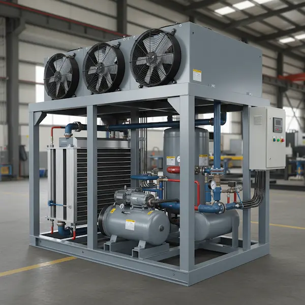
ポンプの選択
ポンプは流量とヘッド圧の両方に適合する必要があります。大きすぎるポンプはエネルギーを浪費します。サイズが小さいポンプは、長い配管やフィルターや熱交換器のような高抵抗のコンポーネントに水を押し流すことができません。ポンプの可変周波数ドライブは、より一般的になってきています。これは、実際の需要に基づいて流量を調整するもので、電力を節約し、摩耗を減らします。.
拡張性と柔軟性
配管は温度変化により伸縮する。硬い接続は、継手、バルブ、チラー自体にストレスを与えます。防振継手や伸縮継手などの柔軟な接続部は、動きを吸収し、時間の経過とともに漏れが発生する可能性を低減します。.
電気的統合
チラーへの電力供給は、利用可能なブレーカーがあるだけではありません。産業用チラーシステムを統合する電気的側面には、調整、保護、そして時にはユーティリティの関与が含まれます。.
負荷計算
チラーは、特に始動時に大きな電流を消費する。施設は、既存の電気サービスが追加負荷を処理できるかどうかを知る必要があります。すでにサービス限界に近い工場に150トンのチラーを追加すると、サービスのアップグレードが必要になるかもしれません。.
制御配線
電力だけでなく、チラーには制御配線も必要だ。これは、工場のビル管理システム(BMS)やプログラマブルロジックコントローラ(PLC)に接続される。チラーはポンプ、冷却塔、時にはプロセス機器そのものと通信する必要がある。ここでの連携不足は、チラーは稼動するがポンプは稼動しない、あるいは冷却塔のファンがチラーから独立して回転し、エネルギーを浪費して温度変動を引き起こす、といったシナリオにつながる。.
一般的な制御信号
- ビルディングオートメーションからの有効化/無効化
- 設定値調整(リモートリセット)
- アラーム監視と通知
- フロー検証インターロック
冷却塔と排熱
を使用するシステムの場合 水冷式チラー, さらに、冷却塔や流体クーラーという追加コンポーネントがある。この部品は最初の計画では見落とされがちだ。.
タワーの位置と補給水
冷却塔は、十分な気流があり、ドリフトによって近隣の設備や歩行者に迷惑をかけない場所に設置する必要がある。また、冷却塔には、蒸発した水を補給するための一定の水源である補給水も必要です。施設の水圧や流量が十分でない場合、貯蔵タンクとブースターポンプが必要になることがある。.
冬季営業
寒冷地では、冷却塔の凍結防止が必要です。これは、ベースンヒーター、ドライ運転戦略、シャットダウン期間中のタワー排水などを意味する。冬季の運用を考慮せずに冷却塔を設置した施設では、最初の凍結時に慌てふためくことになります。.
既存システムとの統合
新しい冷凍機が単独で稼働することはめったにない。既存の機器のネットワークに加わることになり、他の機器との連携がうまくいくかどうかで、統合がシームレスに感じられるか、問題があるかどうかが決まる。.
パラレルオペレーション
すでにチラーが設置されている場合、新しいユニットは並列で運転されるかもしれない。そのためには、慎重な配管構成(一次-二次ループが一般的)と、負荷に応じてチラーをシーケンス制御する必要がある。適切なシーケンシングが行われないと、一方のチラーが稼動している間、もう一方はアイドルになったり、部分負荷で両方が非効率的に稼動したりする可能性がある。.
冗長計画
このチラーは増設用なのか、それともバックアップ用なのか。バックアップ用であれば、配管とバルブは、一方のユニットが稼動している間にもう一方のユニットを修理できるように、分離できるようにする必要がある。追加能力用であれば、配電系統は組み合わされた流量を処理する必要がある。.
試運転とテスト
統合は、システムが実際の動作条件下でテストされるまで完了しない。生産スケジュールがタイトな場合、このフェーズが短縮されることもあるが、スキップすると後で問題が発生する傾向がある。.
機能テスト
各コンポーネントは、ポンプ、ファン、バルブ、制御装置など、システム全体が作動する前に個別にテストされる必要がある。そして、低負荷、高負荷、段階間の移行、あらゆる故障シナリオなど、運転範囲を通してシステムを運転する。.
バランシング
水流は、接続されているすべての機器間でバランスがとれている必要があります。あるゾーンは流量が多すぎるのに、別のゾーンは流量が少なすぎるということは、驚くほどよくあることです。バルブのバランシング、圧力計、流量を設定するための計画的なアプローチがそれを防ぎます。.
よくあるご質問
既存の工場に産業用チラーシステムを組み込むにはどれくらいの時間がかかりますか?
計画から試運転まで、複雑さにもよりますが、一般的なプロジェクトは3ヶ月から8ヶ月かかります。電気系統のアップグレード、配管の引き回し、許認可の取得など、現場特有の要因によって期間が延びることもあります。.
自分でチラーを設置できますか、それとも外部の業者が必要ですか?
設置工事には、電気、配管、制御の各工事が含まれ、通常、免許を持った請負業者が必要である。ほとんどの施設は、配管を担当する機械請負業者、電力を担当する電気請負業者、自動化を担当する制御インテグレーターと協力する。.
チラーを統合する際、最もありがちなミスは?
チラー本体と将来のメンテナンスアクセスに必要なスペースとクリアランスを過小評価している。また、チラーと既存のビルオートメーションとの間の制御の調整を怠ると、運用上の頭痛の種となる。.